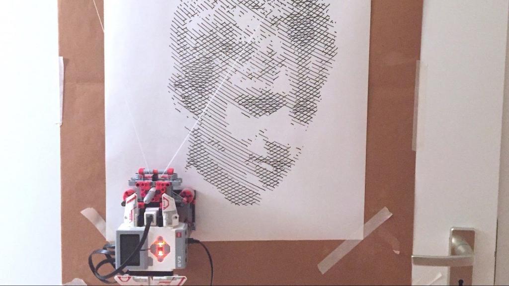
After long nights of hard work I finally have vertical plotter that makes recognisable illustrations. In this tutorial I’m sharing my discoveries so you can build one yourself. In another post on my blog I shared a full tutorial with building instructions.
Step 1: get the right spindle.

My first hunch was to use a large spindle, so the relative increase in diameter with a layer of cord would be minimal. A varying diameter makes the math a lot more complicated. The second spindle looked best because it had the smoothest surface. The others had all kinds of ribs. I made several generations with the second spindle. The problem was, though that the motor had to push a really big load. Because, with the spindle diameter, the lever length and thus the torque increases. So I had to add two gears to increase the force. Also, when just using the large spindles without the gears, the internal motor inertia is not enough to keep the robot in place on the vertical surface. It would slowly uncoil and descend. Another problem with that spindle was, that it wasn’t part of the original 31313 set. So I went and looked for a smaller spindle. The simple red bush proved to be the solution, but only after I found the right thread…
Step 2: find the right thread

I tried many different cords. I was looking for thin and strong, because a thick thread makes the diameter of the spool change a lot when it’s rolled up. As I was counting degrees for movement, this would mean a bad distortion of the drawing. The first thread (the brown) was nice and thin, but broke after 3 drawings. It nearly cost me my brick. The second one, thick white was stronger, but so hard that it dented the soft lego parts and so thick that I had to use a big spool to avoid the change in diameter. This in turn required a gearbox which was imprecise and lossy. Only after a year of failed experiments I had the idea of using dental flos. Thin, strong, cheap, and not all too elastic. A little elastic is ok, as the increased length of the thread, due to stretch would compensate for the increased diameter on the spool.
Step 3: Build the model
I thought gravity would keep the pen in position but I forgot about impulse. A pen down below gave really imprecise and wobbly lines. That was cool for the very first experiment. It even made my beard look better. But ultimately it was a bad idea.
Step 4: build the model and run the program from the brick

During development I was coding on my laptop while the robot was drawing. After some time, though, when the robot was running stable I closed my laptop and went to other stuff while the robot was drawing. That was a bad idea. Because I was coding on ev3dev, I ran the program from the command line. And Linux terminates programs run from the command line if the command line gets a time-out. The result was that the program stopped in the middle of a drawing. And when an ev3dev program stops, the motors keep running at the speed they are set to, they don’t stop automatically. This resulted in the robot driving all the way up to the top right corner of the door, making a hard-to-clean sharpie stain and then being catapulted all the way to the left on the floor. I was really lucky that it landed on relatively thick rug…

