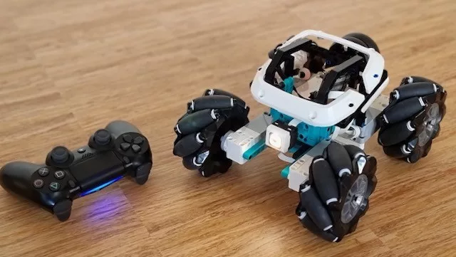
The new LEGO hubs support gamepads from the official LEGO software but only with Scratch/Word Blocks and via a PC in streaming mode. When you need lag-less remote control and precise motor timing, this type of connection is just excruciatingly slow. This article shares how we connected a PS4 controller to a Robot Inventor and SPIKE Prime hub without lag.
Technical background information on Bluetooth and gamepads
You might ask: why did LEGO only allow the gamepad via a PC in streaming mode? Doesn’t it have Bluetooth? The problem is that there’s Bluetooth and Bluetooth. More specifically, there is Bluetooth Classic (BTC, BR/EDR) and Bluetooth Low Energy (or BLE).
Most gamepads use Bluetooth classic. And the LEGO hub has a chip that can do Bluetooth Classic (BTC). But there’s a catch: the hub runs an implementation of Micropython and has a firmware Bluetooth stack that limits BTC. The stack only runs the RFCOMM protocol – a wireless serial port – and you can only use that protocol to access the Micropython REPL. In all likelihood, LEGO will never change this setup because it is core to the communication with the LEGO apps. The bright side is that the Bluetooth Low Energy (BLE) protocol is accessible for us hackers. In other articles, I have shown how to use that to connect to an Android app or to connect to other LEGO hubs. Alas, most gamepads don’t support BLE. Long story short: the only way to work around this limitation is with some extra hardware.
Setup for connecting a PS4 gamepad to a Spike or Robot Inventor hub
To work around these Bluetooth limitations, we used a simple ESP32 chip. Any ESP32 board will work, but we have developed a dedicated LEGO-compatible version: the LMS-ESP32. The LMS-ESP32 chip runs firmware using the BluePad32 library that connects to any gamepad in pairing mode and captures the data. We then connected a LEGO PoweredUp or Wedo wire to the LMS-ESP32 board that feeds the gamepad data into the LEGO hub. The beauty of this setup is that the wire also powers up the ESP32 from the LEGO battery.
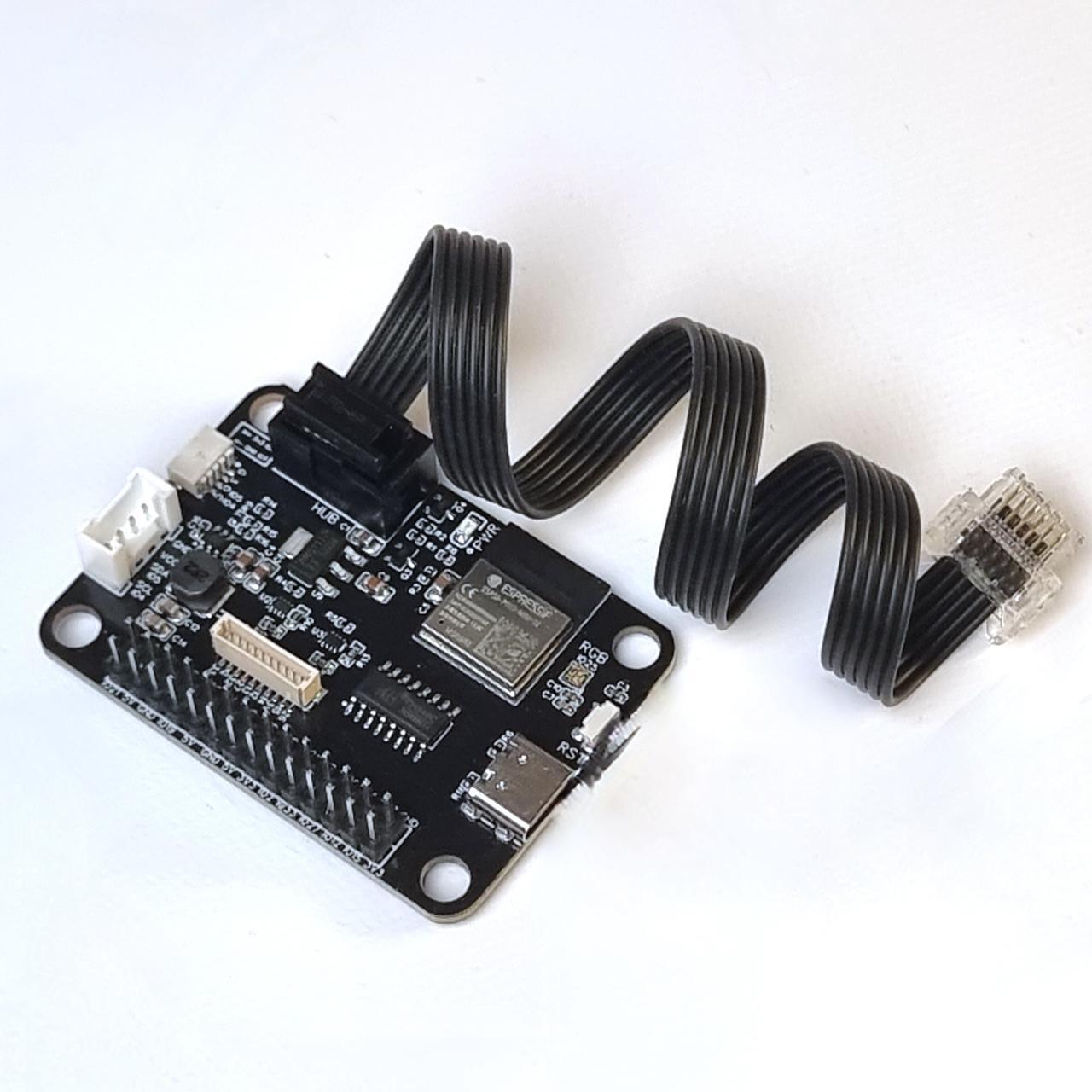
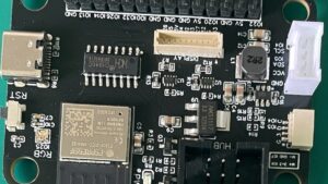
LMS-ESP32 board for SPIKE and MINDSTORMS (LMS-ESP32-v2.0)
This all-new MicroPython expansion board for LEGO MINDSTORMS Robot Inventor, Spike Prime, and EV3. You can easily connect this LMS-ESP32 board to your LEGO robot and use it as an interface to a limitless range of third-party electronics. You can now connect any protocol to your LEGO Robot: I2C, UART, SPI, WS2812, Neopixel, I2S, WiFi, Bluetooth Classic, BLE, Bluetooth HID, Hobby Servo PWM, and m…
If you have an ESP32 laying around, you can use that too. The most popular board is the M5 stick. In that case, use the wiring from the table below.
| SPIKE / MINDSTORMS Hub | ESP32 |
|---|---|
| 1 – M- | nc |
| 2 – M+ | nc |
| 3 – GND | GND |
| 4 – 3v3 | Vin |
| 5 – Tx | rx_pin=18 |
| 6 – Rx | tx_pin=19 |
Apart from the chip, you need a Bluetooth gamepad. PS3 will not work, and neither will the old XBOX 360. But Nintendo Switch, PS4, PS5, Xbox One work.
Finally, this project requires some coding. So we’ll assume you have git installed and python3 with pip. Some basic Python knowledge will go a long way too.
Step by step guide for connecting the gamepad directly to Spike or Robot Inventor
Time needed: 15 minutes
Connecting
- First, we will flash the modified Bluepad firmware on the ESP32.
To do so, Connect the LMS-ESP32 to your PC with a USB cable.
- Flash the firmware with the web-based firmware flasher
Select
BluePad32 for LMS micropython projectsfrom the LMS_ESP Installer. Follow the steps that are shown on the screen. Choose the correct serial port. On my mac, it is usually/dev/cu.usbserial-143220. You can use this web-based installer to revert back to MicroPython firmware.
Skip to step 6. Steps 3 to 5 show the manual flashing process. - Install the esptool.py
Type
pip install esptoolin a terminal window. The full esptool guide is here. - Get our firmware for the LMS-ESP32
Clone the repository with
git clone https://github.com/antonvh/generic-lms-esp32-uart-fw - Now flash the firmware onto the ESP32
In the command below replace the location of the port with the port on your computer. On my mac, it is usually
/dev/cu.usbserial-143220. The full command is this:esptool.py -p /dev/cu.usbserial-143220 -b 460800 --before default_reset --after hard_reset --chip esp32 write_flash --flash_mode dio --flash_freq 40m --flash_size detect 0x10000 build/app-template.bin 0x1000 build/bootloader/bootloader.bin 0x8000 build/partition_table/partition-table.bin - Connect the flashed LMS-ESP32 to your Robot Inventor or Spike Prime hub
Our kit comes with a wire and you don’t have to worry about the connection. If you build your own, check the wiring table above.
- Connect the hub to your PC or Mac
Open the LEGO software and connect your hub. You can use Bluetooth or a USB wire. I prefer USB.
- Create a new Python program.
Press code, click new, and choose ‘python’
- Install mpy-robot-tools
Copy the installer script from GitHub and paste it into the Python program you just created. Note that GitHub has a handy copy button in the top-right of the script!
Run the pasted program once. It can look like the program freezes, but it takes a long time to download and run. You can check the console for output. The console is at the bottom of the screen of your LEGO app.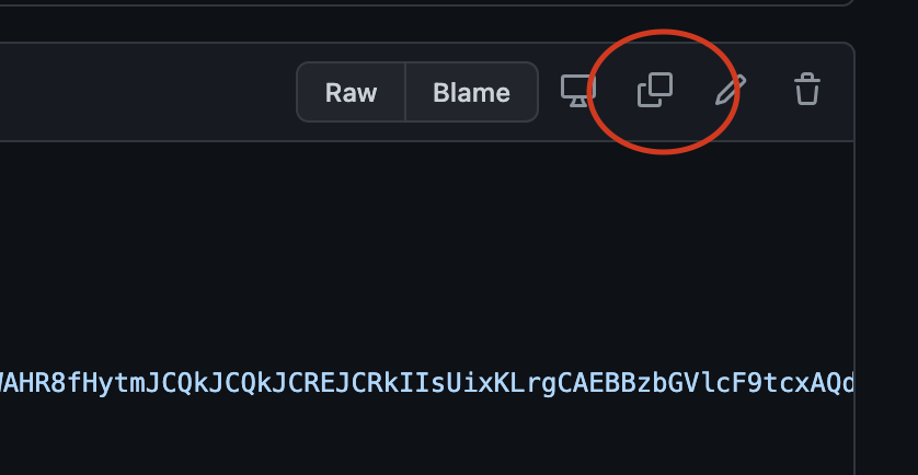
- Reboot the hub
Once the program has run, turn the hub off and on again. Ensure that the LEGO software does not ‘update’ the hub. If it does, cancel and disconnect.
- Run the test program
Clear the contents of the python file you used to install mpy-robot-tools and paste the gamepad test program to test the connection to the LMS-ESP32 board.
- Pair the gamepad with the LMS-ESP32 chip.
On the PS4 controller, you have to hold down the ‘Share’ and PS buttons for a few seconds. As soon as the gamepad is paired, the output should start showing the stick and button positions.
- Now write your program!
Explore the bluepad examples on GitHub and be sure to ask questions on Facebook and Patreon.
Which commands are available?
The Bluepad32 firmware for LMS-ESP is based on the marvelous BluePad32 project. We extended this project with the support for the UartRemote/SerialTalk commands that can be accessed from Lego Spike MicroPyhton. After initialization of the SerialTalk library using this code
from projects.mpy_robot_tools.serialtalk import SerialTalk
from projects.mpy_robot_tools.mshub import MSHubSerial

ur = SerialTalk( MSHubSerial('D'), timeout=20)
The following UartRemote/SerialTalk commands are available:
ur.call('connected')
Checks whether a Gamepad is connected. Returns 1 when connected
ur.call('gamepad')
Returns the status of the Gamepad with 6 parameters: (buttons,dpad,axisX,axisY,axisRX,axisRY)
ur.call('led','B',led_val)
Sets LEDs on the Gamepad (some gamepads support 4 LEDs) to the binary value led_val
ur.call('rumble',2B',force,duration)
Initiates the rumble motor in the Gamepad with the given force and duration.
ur.call('i2c_scan')
Returns the addresses of connected I2C devices. Note: returns a byte array.
ur.call('i2c_read',address,len)
Reads len bytes from I2C device (connected to the Grove port) at address adress
ur.call('neopixel','4B',led_nr,red,green,blue)
Sets led number led_nr to color (red,green,blue). Use led_show to display the LEDs.
ur.call('neopixel_show)
Shows current led configuration.
ur.call('neopixel_init','2B',number_leds,pin)
Initiates NeoPixel with number_leds LEDs on Pin pin. By default the number if LEDS is 64 on pin is 12.
ur.call('servo','>Bi',servo_nr,pos)
Sets servo number servo_nr to position pos. Mapping is servo 1, 2, 3, and 4 on pins 21, 22, 23, and 25. Currently, only servo1 is supported.
What’s next after connecting the gamepad
We haven’t gotten around to fully documenting all possibilities of the firmware we developed. We would appreciate some help there! In the meantime, you can look at the code of the central program file to figure out what call you can try. Also, check out the possibilities in mpy-robot-tools by scanning through the code here.
If you enjoy this guide, be sure to subscribe on Youtube. You can also check out Patreon for access to more building instructions. Patreon supporters get priority answers when using my guides. Share your work and let us know what you’ve made!


Hello Anton:
After much trial an d error I think this is what I have manged to get setup on my Windows 10:
– installed the ESP-IDF into VS Code
– upgrade my pip
– installed esptools
– I have a directory C:\Users\Wareman\Documents\ESP\
– I have a subdirectory for the firmware I need to flash to the ESP32 C:\Users\Wareman\Documents\ESP\generic-lms-esp32-uart-fw
– the LMS-ESP32 is connected to com6
– VS Code is set to use UART
If I try flashing from the ESP directory or from the generic-lms-esp32-uart-fw I get this error — flasher_args.json file is missing from the build directory, can’t proceed, please build properly!!. I tried your sample flash code but that also did not work. I do not know what parts of the code needs changing.
Any help would be greatly appreciated.
Mike,
Interesting. I’ll look into it. Maybe I should check in flasher_args.json into git. I hope that fixes it.
I think I figured out where the instructions were unclear. Just use the terminal instead of the flash button in the VS Code interface.
I tried:
This worked for me.
/repeated my steps and still cannot get vs code to work properly. I think part of the problem is that I am not connecting to the esp32-lms board. I see that it is connected to my computer using either com6 or com8 depending on which USB port I am using. The only way I am able to know that I am connected to the esp32-lms board is through webrepl. The other thing is that VS code wants to know what esp32 board I am using.
Is it possible to use the webrepl to install/upload the generic-lms-esp32-uart-fw firmware or a different tool?
Thanks for your perseverance. I usually do everything on Mac. But I have an old PC too and I’ll try to replicate everything there tonight.
Hello Anton:
After my initial failure to do the firmware update I had installed and Espressif IDF extension. I now uninstalled the extension and started over. I needed to be in the folder where the generic firmware was copied to. Pipenv install esptool did not work for me, but pip install esptool did work. I then ran your code listed above. This is the output I received. I am assuming that the output says that the firmware was successfully up loaded to the ESP32. My next problem is getting the PS4 gamepad to connect to the ESP32. Other than running the sample program how do I know that the gamepad did connect to the ESP32?
output from VS Code as it built and uploaded the firmware to the ESP32
esptool.py v3.3
Found 7 serial ports
Serial port COM9
COM9 failed to connect: could not open port ‘COM9’: OSError(22, ‘The semaphore timeout period has expired.’, None, 121)
Serial port COM8
Connecting…..
Chip is ESP32-D0WD (revision 1)
Features: WiFi, BT, Dual Core, 240MHz, VRef calibration in efuse, Coding Scheme None
Crystal is 40MHz
MAC: 1c:9d:c2:c2:f2:f0
Uploading stub…
Running stub…
Stub running…
Changing baud rate to 460800
Changed.
Configuring flash size…
Auto-detected Flash size: 4MB
Flash will be erased from 0x00010000 to 0x000ddfff…
Flash will be erased from 0x00001000 to 0x00007fff…
Flash will be erased from 0x00008000 to 0x00008fff…
Compressed 843600 bytes to 455358…
Wrote 843600 bytes (455358 compressed) at 0x00010000 in 10.8 seconds (effective 626.0 kbit/s)…
Hash of data verified.
Compressed 25264 bytes to 15784…
Wrote 25264 bytes (15784 compressed) at 0x00001000 in 0.9 seconds (effective 234.8 kbit/s)…
Hash of data verified.
Compressed 3072 bytes to 103…
Wrote 3072 bytes (103 compressed) at 0x00008000 in 0.1 seconds (effective 465.1 kbit/s)…
Hash of data verified.
Leaving…
Hard resetting via RTS pin…
PS C:\Users\Wareman\esp\generic-lms-esp32-uart-fw>
Press and hold the Share and PS buttons on the gamepad for a while. The light will start flashing white. When the light turns blue, you’re connected.
That is what I have been doing. The light does not turn blue. As a different test I am able to connect the Controller to my iPad. I will keep trying. Maybe just like doing the firmware it will work one of these tries. I was also wondering if resetting the Controller to factor setting would help.
Thank you for all your help.
Hi Anton,
Good evening, I am excited to give this a try, though I was curious as to why the installer script uses the pyhuskylens code, I presume its the same as:https://github.com/antonvh/LEGO-HuskyLenslib/blob/53695d6a8a0c7aeb84342bb7d9de0fb8c7dccd4d/Library/pyhuskylens.py ?
I’d like to get the huskylens in the future, though didn’t see how it is relevant to this article, other than code reuse and perhaps loading logic to support the blue tooth connection?
Thanks for all your work!!!
I just figured I’d include all my work in mpy-robot-tools. But no, it’s not needed for most projects.