Where the screen of the Mindstorms EV3 had a resolution of 178 x 128 pixels, the screens of the Lego Mindstorms Inventor and Lego SPIKE Prime hubs only have a resolution of 5×5 pixels. Wouldn’t it be nice to add a touch-sensitive TFT screen to the Lego Hubs? Keep reading if you are curious how we use the Wifi LMS-ESP32 Micrpython board to achieve this.
Overview of the LVGL (Light and Versatile Graphics Library) Library
You will find many graphics libraries for driving TFT screens, but most of them are limited to basic graphics functions such as drawing lines, rectangles, and text. Building a usable GUI from these basic components is quite a hassle. It becomes even more complex if you would like to add interaction with a touch-sensitive screen.
We propose to use the LVGL (Light and Versatile Graphics Library) library, which not only comes in a C-version but also in a MicroPython version that integrates nicely with our MicroPython eco-system on both the LMS-ESP32 as well as the Lego hubs.

Using LVGL, you can choose from a large variety of widgets. For instance, a meter widget shown to the left or buttons, labels, sliders, etc. LVGL takes care of handling the touch events on the different widgets. You decide what should happen when a button is clicked by using call-back functions in your code.
To get an idea of what widgets are available in LVGL, you can look at the LVGL examples.
Basic Micropython LVGL setup with LMS-ESP32
The default firmware that comes with the LMS-ESP32 already has the LVGL Micropython library integrated. There is no need to load additional software libraries on the LMS-ESP32.
The code below initiates the LVGL library for the ILI9341 TFT screen and touch panel. Because the LVGL library uses the 4MByte PSRAM present in the ESP32-WROVER module, running this code twice results in an error. We advise you to reset the LMS-ESP32 before running the code below.
import espidf as esp
import lvgl as lv
from ili9XXX import ili9341,LANDSCAPE
from xpt2046 import xpt2046

#init TFT display
disp = ili9341( miso=12, mosi=13, clk=14, cs=15, dc=23, rst=25,
                backlight=-1,power=-1,width=320, height=240, rot=LANDSCAPE)
# use same SPI as display, init touch
touch = xpt2046(spihost=esp.HSPI_HOST,cs=26,transpose=False,
                cal_x0=3865, cal_y0=329, cal_x1=399, cal_y1=3870)
Once the screen is initialized, generating a GUI from the widgets in the LVGL library is very easy. For example, drawing a button in the middle of the screen is as easy as follows:
scr =  lv.scr_act()
btn = lv.btn(scr)
label = lv.label(btn)
label.set_text("Button")
btn.center()
Demo
In the tutorial video below, the LMS-ESP32 drives a TFT screen using LVGL with a linear slider and a meter widget. The values of the widgets are being sent from the Lego hub using the UartRemote library.
Code on the LMS-ESP32
All the code running on the LMS-ESP32 is shown below. The first few lines of the code initialize the TFT screen (which has an ILI9341 controller) and the touch display (with an XPT2046 controller). The calibration values for the touch panel are just taken from an example and should be good to go.
from uartremote import *
import espidf as esp
import lvgl as lv
from ili9XXX import ili9341,LANDSCAPE
from xpt2046 import xpt2046

#init display
disp = ili9341(miso=12, mosi=13, clk=14, cs=15, dc=23, rst=25,
               backlight=-1,power=-1,
               width=320, height=240, rot=LANDSCAPE)
# use same SPI as display, init touch
touch = xpt2046(spihost=esp.HSPI_HOST,cs=26,transpose=False,
                cal_x0=3865, cal_y0=329, cal_x1=399, cal_y1=3870)


arc = lv.arc(lv.scr_act())
arc.set_range(0,360)
arc.set_bg_angles(0,360)
arc.set_size(150,150)
arc.align(lv.ALIGN.CENTER,0,0)


slider = lv.slider(lv.scr_act())
slider.set_width(200)
slider.align(lv.ALIGN.CENTER,0,-100)
slider.set_range(0,360)

label1 = lv.label(lv.scr_act())
label1.set_long_mode(lv.label.LONG.SCROLL_CIRCULAR)         # Circular scroll
label1.set_width(150)
label1.set_text("Demo using LVGL library. ")
label1.align(lv.ALIGN.CENTER, 0, 100)
ur=UartRemote()

def show_angle(angle):
    arc.set_value(angle%360)
    slider.set_value(angle%360,1)

ur.add_command(show_angle)

ur.loop()
Next, three different widgets are initialized on the TFT screen.:
- arc-widget
We set the arc range between 0 and 360. Furthermore, by changing the start and stop angles to 0 and 360, respectively, we obtain a full 360 arc, After setting the size to 150, the arc widget is moved to the middle of the screen. - slider-widget
We set the slider’s width to 200, center it horizontally, move it to the top of the screen, and finally, set the range between 0 and 360. - label-widget
This widget is not necessary for the demo, but just shows a scrolling text
Next, the function show_angle is defined that sets the values of both the arc as well as the slider to the values angle. We add this function to the UartRemote commands, and finally, we call the UartRemote `ur.loop()`, which is waiting for any command to be received through the UartRemote link.
Code on the Lego Mindstorms
Below you find the code running on the Lego Mindstorms Inventor.
from projects.mpy_robot_tools.uartremote import *
import hub

ur=UartRemote('A')
motor = hub.port.B.motor


motor.mode([(2,0)]) # absolute position, raw units

motor.preset(0)
while (True):
    m=motor.get()[0]
    ack,val=ur.call('show_angle','repr',m)
We first import the UartRemote library. In this example, we connect the motor to port B. By setting the motor.mode to [(2,0]), we use absolute positions in raw units. Then we can use the motor.get() method to obtain the absolute angle of the motor stored in the first element of the returning array. That angle is used to call the show_angle function remotely on the LMS-ESP32 using a UartRemote library call command
Hardware
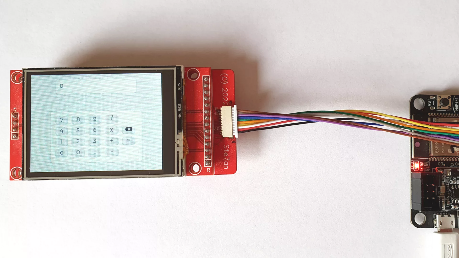
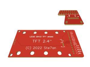
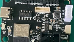
In this tutorial, we use a TFT screen with a resistant touch panel with a resolution of 340×240 full-color pixels. We deploy a single SPI (Serial Peripheral Interface) interface for both the TFT screen and the touch panel, each having its own CS (Chip Select). This limits the number of cables needed to connect the display. We connect the panel with a 1mm pitched 10-wire cable to the LMS-ESP32’s GPIO port. This cable takes much less space than 10 DuPont cables. We designed break-out boards for both the panel and the GPIO connection that accommodate the 1mm pitched connectors. For applications where you do not need touch capabilities, you could use the solder pads for changing the spare wire to switch the TFT backlight.
For prototyping purposes, you can also hook up a TFT display directly. When using the TFT panel with the Touch panel, you need to connect the MOSI, MISO, and SCK signals of the TFT SPI bus with the similar signals of the Touch controller, namely T_DI, T_DO, and T_CLK, respectively. The chip select of the touch panel, T_CS, is still needed as a separate signal. This is shown in the schematic below.

The TFT_CS and TS_CS remain separate signals. The PCB board we provide takes care of these connections and break out on a 10-pin 1mm wire. The other side of this 10-wire cable is connected to the GPIO bus of the LMS-ESP32. The VCC and GND pins are directly connected to the 3V3 and GND pins on the GPIO header of the LMS-ESP32. The mapping of the signals from the display and touch panel to the GPIO pins on the LMS-ESP32 board is shown below:

Things can be simplified when you deploy only the TFT screen without the touch panel. Then you do not need to make the connection with the T_CS, T_DI, T_DO, and T_SLK pins.
Shopping list
What should you order to get started? You should collect a touch-sensitive TFT screen with an SPI interface at your favorite store. We can provide you with the break-out PCBs, the connectors, and the cables. If you have a stable hand, you can solder the connectors yourselves or order the PCBs pre-soldered.
Advanced usage of this TFT board
Mr Jos uses our TFT PCBs and an LMS-ESP32 hooked up to lego Mindstorms EV3 to create beautiful GUIs for his projects. Look at his latest creation: a Lego Pin sort machine where you can follow the sorting progress on the TFT screen.
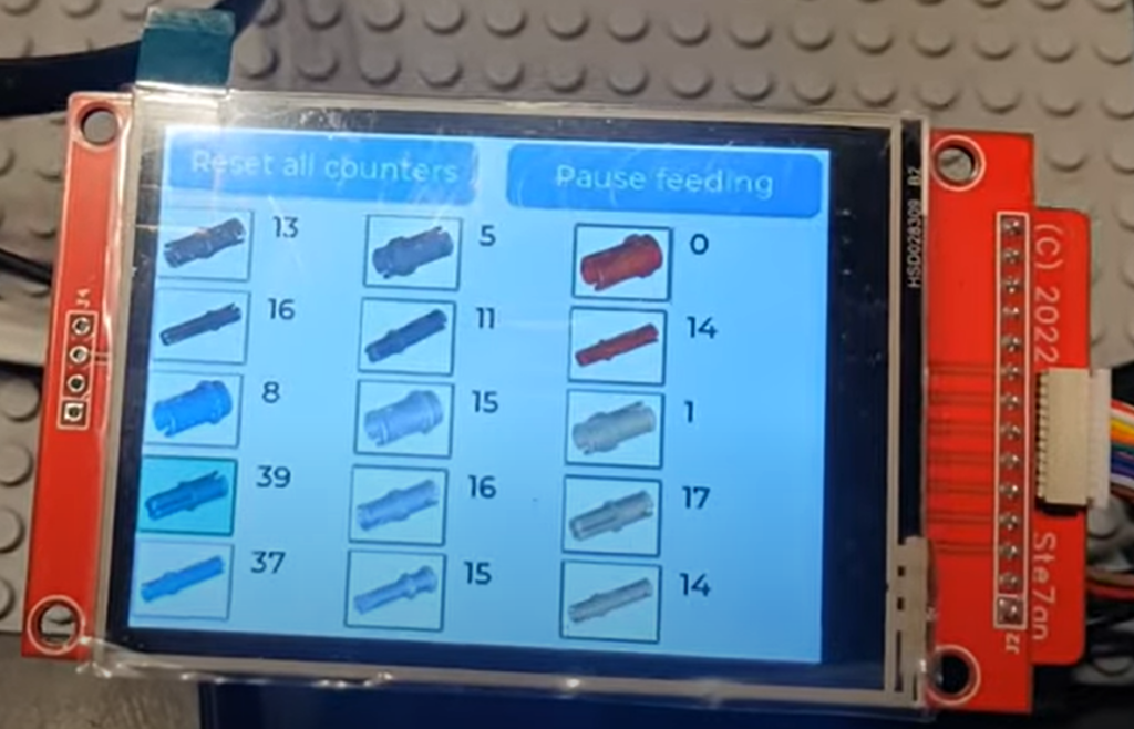
He created icons of all the different Legopins and shows them in the GUI.


hello, I want to connect the display to the ESP 32 and got confused about the purpose of the contacts. Please write the purpose of the contacts between the display and the ESP 32 and the touch sensor.
Hello Andrey, in the hardware section above, I added a description of the pins on the TFT/touch panel and how these are mapped to the GPIO pins of the LMS-ESP32. I hope that this will help. My experience is, that when you use normal Dupont cables to make the connection, you end up with a bunch of cables that is hard to handle in a lego project. That is the reason we decided to create the breakout boards using the flexible 10-wire 1mm pitch cable. The breakout boards make all the necessary connections to use both the TFT and the Touch panel simultaneously while using only 10 wires to connect it to the LMS-ESP32.
Hello, the indicator is working, thank you. Now I want to connect esp32 and hub via LPF2 connector. Please check the connection: 6 pin: RX(18pinESP32), 5 pin:TX(19pinESP32), 4 pin (+3.3V), 3 pin (GND), 2 pin (M2), 1 pin (M1). https://philohome.com/wedo2reverse/connect.htm
Hi, good that you succeeded in getting a widget on the TFT screen. We provide an LPF2 cable with a 2×3 header with the LMS-ESP32 kits. The numbering you mention is correct. Of course, when using an ESP32 devkit, you could connect pins 5 and 6 of the LPF2 to any of the ESP32 GPIO’s and define the pins in the UartRemote initialization correspondently.
Hi Ste7van,
Just soldered the HW an I am now trying to get your example to work.
When I run your code from above on the LMS-ESP32 I get the follwoing error:
MPY: soft reboot
Single buffer
Traceback (most recent call last):
File “”, line 8, in
File “ili9XXX.py”, line 585, in init
File “ili9XXX.py”, line 161, in init
File “ili9XXX.py”, line 239, in disp_spi_init
RuntimeError: Failed initializing SPI bus
do you have a clue how to solve this?
Thanks!
Wim
Hi Wim,
have you tried to to do a hard reset (small button on LMS-ESP32). The SPI bus is claimed until a hard reset, so run the code just once after hard reset.
I hope this helps,
Stefan
Hi Stefan,
I added your code to boot.py iso main.py an now I get (after reset):
rst:0x10 (RTCWDT_RTC_RESET),boot:0x17 (SPI_FAST_FLASH_BOOT)
configsip: 0, SPIWP:0xee
clk_drv:0x00,q_drv:0x00,d_drv:0x00,cs0_drv:0x00,hd_drv:0x00,wp_drv:0x00
mode:DIO, clock div:2
load:0x3fff0030,len:4396
ho 0 tail 12 room 4
load:0x40078000,len:13884
load:0x40080400,len:3340
entry 0x40080618
Double buffer
ILI9341 initialization completed
So the SPI problem is gone 🙂
However, the display is not lighting up. Do I need to bridge any of the pads at the back of the LEGO SH1.0 board? I do measure 3.3V on both the Vcc and the D/C pin of the board.
Thanks again!
Wim
Hi Wim
yes, you need to shorten the pad between 3v3 and LED at the back of the TFT carrier board. For testing you can run the program in the section Basic Micropython LVGL setup with LMS-ESP32, above. I changed the first line in the second block of the program. It should work now.
When powering on the LMS-ESP32 with the display connected, you should see the backlight automatically turned on. When you do not plan to use the SD card on the back of the screen, you could also use an IO pin to enable the backlight.
Thanks Stefan, it works now!
Hi Wim, good that it works now! Would you be so kind as to briefly keep us updated on your project. I am curious what your application is for the display. Thanks.
I’m trying to use PUPRemote + Pybricks instead of UartRemote. Initializing a touch breaks communication between the LMS-ESP32v2 board and the technic hub (Failed to connect to hub
Checking heartbeat, but not connected. Initializing.) If I comment out this part with xpt2046, it connects. Any workaround?