Almost three years ago, we introduced the LMS-ESP32 board. It quickly became a favorite among hobbyists for extending their Lego Robot hubs. After building many projects with it ourselves and gathering customer feedback, we developed a new version. We’re excited to announce its release! In this blog post, we’ll highlight the changes and dive into the electronics behind them.
What’s New in LMS-ESP32 Version 2?
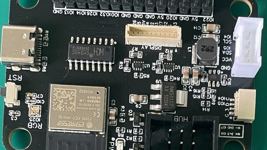
- Smaller ESP32-PICO-V3 MCU with 8MB flash and 2MB PSRAM
- Improved power source transformation and switching
- On-board NeoPixel added
- 10-pin 1mm connector for graphics display (future project!)
- Qwiic mini connector for sensors
- USB-C connector replaces Micro USB for better reliability
- Integrated on-board buck converter replaces prebuilt module
New MCU: ESP32-PICO-V3
The standout change is the smaller ESP32 MCU. The original LMS-ESP32 used the ESP32-WROVER MCU with 4MB flash and 4MB PSRAM. The new version uses the much smaller ESP32-PICO-V3, which has 8MB flash and 2MB PSRAM. This package is about one-third the size of the ESP32-WROVER. We remapped some GPIO pins to ensure compatibility with the robot hub.
Improved voltage conversion and source switching
The LMS-ESP32v2.0 board features two power rails: a 5V rail for components like NeoPixels or servo motors, and a 3.3V rail for the ESP32 microcontroller and CH340 UART-to-USB converter. Our goal with the new power design is to keep everything running seamlessly, while you plug devices in and out.
Buck Voltage Converter
The robot hubs provide two power sources: a limited-current 3.3V source and an up-to-8V motor output source delivering over 1A of current. We use a TPS563200 step-down regulator to convert this motor output to a stable 5V supply for LEDs and hobby servos.
Switching regulators like TPS563200 offer higher efficiency compared to linear regulators, reducing heat dissipation significantly when drawing larger currents:

Automatic power source switching
The 5V rail can draw power from either USB or an on-board buck converter that steps down an 8V source from the robot hub to a regulated 5V. The 3.3V rail gets power from an onboard regulator converting from 5V or directly from the robot hub.
Here’s how the LMS-ESP32v2.0 board switches between power sources:

Switches automatically control based on input voltages. If connected only to USB, it uses USB power. The regulator always supplies the 3.3V if there’s a present 5V source; otherwise, it draws directly from the hub. We use TPS2116 priority power multiplexers for switching between two sources each for both rails without voltage drops:

These chips ensure uninterrupted power supply by switching at configured voltages (2V for the 5V switch and 3.12V for the 3.3V switch).
Added an onboard NeoPixel to show your program status
A small onboard NeoPixel (SK6812) connects to GPIO25, allowing users to choose its application as a visual indicator. It’s also great fun for a hello world program.
Graphics Display Connector for color touch screens
We added a 10-pin JST-SH connector for graphics displays while keeping other GPIO headers free:

This pinout is compatible with our Touch Screen Mounting PCB.
Prototyping the new board
Developing a new board can be tedious. So, we decided to assemble the prototype boards ourselves. This way, we can make small changes during assembly.
We ordered a batch of five PCBs from JLCPCB and sourced the SMD components from LCSC Electronics. LCSC allows us to submit a Bill of Materials (BOM), and they ship the components quickly. For smaller components, we had to order a minimum quantity. As a result, we ended up with over 2,000 components for our prototypes. Small SMD resistors and capacitors usually come in strips of 100 pieces.
We also ordered a solder stencil to easily apply solder paste to the pads. The smallest solder mask measures 380 × 280 mm (about A3 size), which is large compared to our small PCB.

We placed our PCB in a frame made of scrap PCBs with the same thickness. This keeps our PCB fixed when we align the solder stencil. After applying the solder paste, you can see it evenly distributed over all the contacts. Finally, we carefully place and align our components on the PCB.

Some components are really tiny. Below, you can see the TPS2116 voltage switch chips.

We use a homemade hot plate for soldering, heating it to 300 degrees Celsius. Within a minute, the solder paste melts and the components solder together. After about 35 seconds, you notice the solder paste melting. The surface tension of the solder causes smaller components to shift slightly.
Modifications based on the prototypes
In the first prototype (green PCB), we fixed several issues:
- We used a TPSRV-05 ESD protection chip for the USB line, but it was connected incorrectly. After removing the chip, the USB connection worked.
- The power line to the SK6812 NeoPixel wasn’t connected to the 3V3 rail. After hardwiring this connection, the NeoPixel worked.
- The TPS2116 switches prioritized 5V from the buck and 3V3 from the robot. We changed this so that USB power takes precedence over robot power.
Based on our experience with the first prototype, we decided to make these changes in the next prototype (blue PCB):
- Add a 10-pin JST-SH 1mm connector for graphics display.
- Change the order of precedence for power switching.
For the final production version, added some more changes:
- Remove ESD protection on the USB since other pins aren’t protected either.
- Redo trace layout of power lines with much wider traces.
- Place capacitors closer to component power lines.
- Add extra silk layer labels.
Below, you can clearly see reworked power traces (left is old, right is new).

Production of the LMS-ESP32v2
When we submitted the Gerber file to our production company, Shenzhen FlyFun Technology Co., Ltd., their electronics expert spotted a lot of improvement points again. This was super helpful. What we also like about the company is that they can solder through hole components and package the products. If you have ordered a board from us in the past, I believe they add their business card to the shipment.
After we addressed these points, they produced a first batch of the boards, for us to test. On some boards, we spotted an issue with power conversion, so we expanded automatic tests to cover that part of the board too.

Acceptance tests
After producing the LMS-ESP32v2 boards, the production company performs an acceptance test to check all GPIO pins for good connections and short circuits with surrounding pins. Each test involves two units: the Tester Unit (TU) and the Device Under Test (DUT). The program on the TU runs in an endless loop, allowing it to test multiple DUTs.
The TU uses the on-board NeoPixel LED connected to GPIO25 to indicate the test status:
- Orange: A new DUT can be inserted.
- Green (1 second): Test succeeded.
- Red (5 brief flashes): Test failed.
During a test, the NeoPixel LED on the DUT flashes red, green, and blue alternately. Additionally, the TU provides serial output during the test.
Below is an example of a short…

And a successful test result:

Ready for shipping
The new LMS-ESP32v2 boards are ready for shipping. We think it is fun using this new board, and we hope you will use it in your next projects.

